A heartbeat measurement circuit Circuit Diagram Design and build a programmable heart rate monitor in this engineering project. Photoplethysmography - (IR Heart Rate Monitor): This Instructable documents how to create a simple heart rate monitor using Photoplethysmography with an IR phototransistor via transmissive absorption using the Arduino to process the pulsatile data and display live results via a TFT screen. To use… The heart rate monitor Circuit is a device you've most likely heard of before. Chances are you know one or two devices or persons that have heart rate sensors.

The heart rate monitor circuit based on PPG offers a practical and cost-effective solution for measuring heart rates non-invasively. By utilizing simple components and a straightforward design, this project can be expanded and integrated into wearable technologies for continuous health monitoring. Discover how to build a Custom and User Friendly Heart Rate Monitoring device by Using Arduino, OLED Screen, Bluetooth and Smartphone App.
Heart Rate Monitoring using Arduino and Smartphone App Circuit Diagram
The circuit design of Arduino based Heart rate monitor system using Heart beat Sensor is very simple. First, in order to display the heartbeat readings in bpm, we have to connect a 16×2 LCD Display to the Arduino UNO.

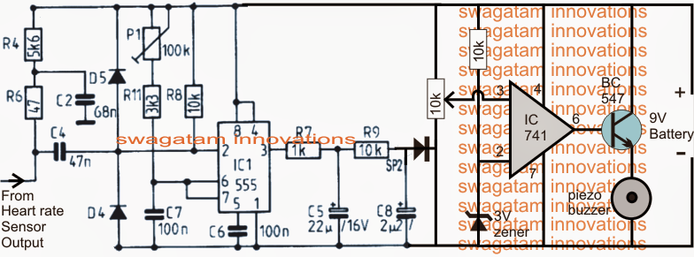
A Heart rate monitor is a simple electronic circuit that monitors the user's heartbeat by indicating the changes in blood volume through any organ of the body which causes a change in the light intensity through that organ. In this article I will comprehensively discuss a relatively accurate electronic heart rate sensor circuit processed by a few discretely wired opamp circuit stages, and subsequently we'll learn how this can be modified for making a heart rate monitor alarm circuit.

(IR Heart Rate Monitor) Circuit Diagram
A Heatbeat Sensor is a monitoring device that measures the heart rate i.e the speed of the heartbeat. A person's heartbeat is the sound of the valves in his heart expanding or contracting as they force blood from one region to another There are two ways to monitor the heart rate: one way is to manually check the pulse either at the wrists or neck and the other way is to use a Heartbeat Sensor. An electrocardiogram (ECG) measures the electrical activity of the heartbeat to show how fast the heart is beating as well as its rhythm. There is an electrical impulse, also known as a wave, that travels through the heart to make the heart muscle pump out blood with each beat. The right and left atria create the first P wave, and the right and left bottom ventricles make the QRS complex. The
