Circuit Diagram Basic Electrical Wiring You can use the solder dot prototyping board for soldering the LEDs on it. Push the LEDs through the adjacent holes on the board. Use the circuit figure below to connect the Arduino LED matrix together. Then, take the positive lead of the first LED and bend it down to the other LEDs and solder the pins which touch each other.

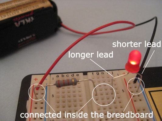
Today I'm going to show you how to create a simple yet customizable LED and battery circuit that's perfect for putting inside your next project. This is a great first soldering project! Follow along with the video to practice your technique. The most basic LED circuit can be made by sandwiching the legs around a coincell battery. Simple Basic LED Circuit. Step 1: 3 Volt Basic LED Circuit With 10 Ohms Resistor. The above diagram shows a 3V LED circuit, in this circuit there are two AA cells are used. When you are operating an LED with 3V you have to use minimum 10 ohms resistor .
How To Make An 8x8 LED Matrix Circuit Diagram
Make the blink LED example. Now that you have the circuit and the code to setup the LED, let's do something a bit more interesting. Let's make the LED blink, which means that we are going to: Power on the LED, wait, Power off the LED, wait, Go back to 1. Here's the code to do that (using our LED connected to digital pin 12). One of the most common LED arrays is the seven-segment display used in applications where you only need to show digits, such as a clock. For example, in the project "Do-It-Yourself Soldering Station with an ATmega8" , I have used a triple seven-segment LED array to display and set the temperature of the soldering iron.

First, connect GND from your MKR1000 to your 220 ohm resistor(s). (the more, the better!) Then, connect the other end of the resistor(s) to the Cathode of all your LEDs. Great your almost there! Now, on the Arduino MKR1000, their are 7 pins, 1 through 7, excluding 0. So basically, connect your LEDs in order (ex. 1st LED to 1, 2nd LED to 2, etc.) #led #diyelectronics #circuit 🗳️ How to Build a Simple LED Circuit Using an Arduino In this tutorial, Bryan DeLuca from Maker Build It walks you through the

Easy LED Circuit : 5 Steps (with Pictures) Circuit Diagram
Figure 1: FYM12882AEG LED Array Circuit Diagram Figure 1 displays the circuit inside the 8x8 LED array. As shown, there are eight rows and eight columns in the array. Every row-column pair contains one LED housing. But each row-column pair (there are 64 total) actually contains two LEDs, a green one and a red one (not orange as stated in the