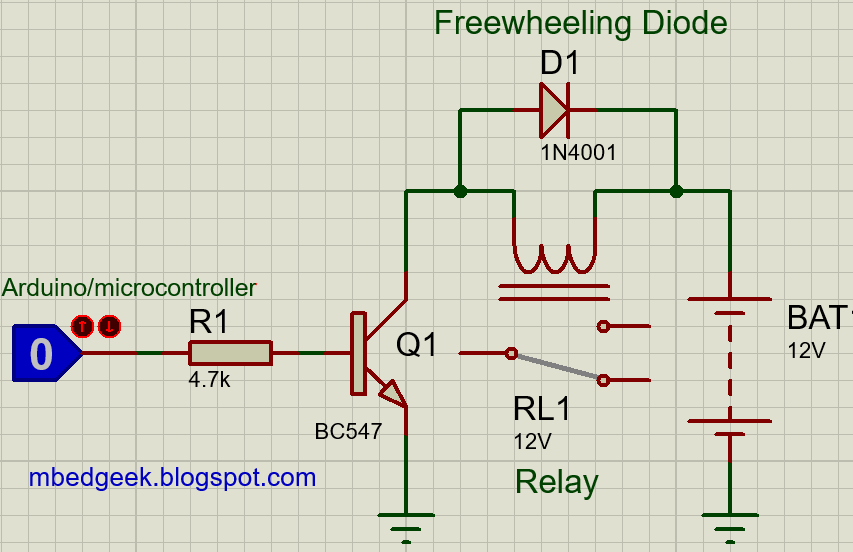
Connect of microcontroller to the Relay Circuit Diagram How does it work? In the above schematic you see a general microcontroller application to control a relay. The microcontroller needs a regulated power supply (5V in this application). GP3 is set as input and allows the microcontroller to read the status of the momentary switch. GP0 is set to output to control the transistor. Where as electrical relays minimum take +5 volts to make a regular connection. We must need an external circuit to drive relays with stm32 microcontrollers. This post is about teaching you what must be used with stm32 microcontroller to driver multiple relays with it. Their are number of methods on how to drive high loads with microcontrollers.

The relay driver circuit using ULN2003 is given below. In this circuit diagram, the pic microcontroller is providing a signal to 4 relays through relay driver IC ULN2003.

Relay Driver Circuit Using ULN2003 and its Applications Circuit Diagram
They can directly interface with microcontrollers due to their very low input current requirements. Therefore, solid-state relays are an ideal choice for microcontrollers and digital circuits.
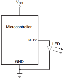
A microcontroller is a low-power logic device. By itself, it is generally incapable of directly driving a relay. A single N-channel MOSFET may be interposed between the microcontroller and relay to increase the available coil current and accommodate relays with higher coil voltages. In this article, we explore a simple MOSFET-based interface allowing an Arduino Nano Every to control a 12 VDC Electromechanical Relays construction and working principle, interfacing circuits with microcontroller using transistors and relay driver IC ULN2003
Relay control by using microcontroller Circuit Diagram
I'm working on a I/O module to control AC, DC motor and lamps by using relays. But I don't know how to control the relays. Some says I should use optocoupler, some says transistor array. I found an optocoupler TLP280, in the figure there is the schematic. Can I use it by supplying 3.3V to control 24V dc motor and some lambs.
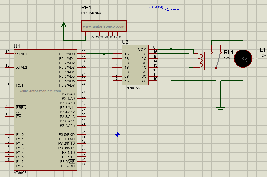
A relay control circuit is essential for controlling high-power devices using a low-power microcontroller. This project demonstrates how to use the 8051 microcontroller to control a relay, which can then switch on or off an external device such as a light bulb, motor, or fan. Relays act as electrically operated switches that isolate the control circuit from the high-power load, providing