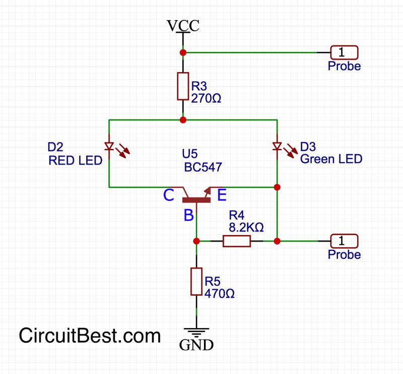
Digital Test Circuit Electronic Production DIY Kit Jiangsu 2020 Pair Circuit Diagram Need to test electronic components but don't have specialized equipment? Try this simple component tester! 🎯 With just a few basic parts, you can easily che
And many things It not just a component tester,but also it is a PWM generator.. Projects Contests Teachers Arduino Components Tester. By Chauhan Vivek R in Circuits Arduino Electronics.. Arduino nano - 1. 16*2 LCD - 1. 9v Battery - 1. 9v Battery cap - 1. PCBs. Resistors ---680R - 3. 470K - 3. 1K - 1. variable resistor 10K - 1. some wires.

DIY super simple electronic component tester Circuit Diagram
DIY super simple electronic component tester June 05, 2021 by Mirko Pavleski. Fork Project Share. The device is capable of testing: PNP, NPN transistors, N or P Channel MOSFET, Diodes, Double diodes, Resistors, Capacitors Materials; Project; Resources; Hardware 1
Component Tester - Test Almost Anything !!: Being an Electronics student or hobbyist, you may have thought of getting a tester that could test almost anything "THE ELECTRONICS COMPONENTS, OBVIOUSLY!!" Electronic Components. 1x 1nF (102) Ceramic Capacitor ; 1x 10nF (103) Ceramic Capacitor ; 4x 100nF (104) Ceramic Capacitor ; 2x 22pF (22
![DIY electronics: [Component tester] Ελεγκτής εξαρτημάτων Circuit Diagram](https://3.bp.blogspot.com/-wrGDTEOGsFc/WazomooJ2TI/AAAAAAAAADg/yqvkOOj-sG0jv900uKeflXtjHoClCeD7gCLcBGAs/s1600/1.JPG)
Test Resistors, Capacitors, Transistors, and ... Circuit Diagram
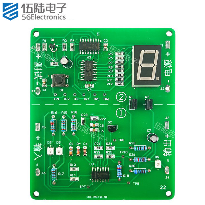
Component tester is an essential tool for electronics component value measurement. Here we have one DIY version using Arduino's chip made by many other hobbyists in the past. Today we will build one version with a better PCB design keeping a minimal version in mind with a combination of SMT and TH components. Learn how to make a DIY components tester at home! This project helps you test electronic components like resistors, capacitors, diodes, transistors, and more with ease. Follow this step-by-step guide to build your own affordable and reliable tester using basic tools and components. Perfect for electronics enthusiasts, students, and hobbyists looking to troubleshoot or organize […]

Principle Behind Electronic Component Tester. For testing an electronic component, first, we need to insert it in a 3 pin socket. Then by pressing a push-button the testing device test the component and gives us some values. These include what is the part, which type of component, pin arrangement, and the value of the component.

Test Almost Anything Circuit Diagram
Component tester is an essential tool for electronics component value measurement. Here we have one DIY version using Arduino's chip made by many other hobbyists in the past. Today we will build one version with a better PCB design keeping a minimal version in mind with a combination of SMT and TH components. The code is open source and can be found on the web, some modifications are made to

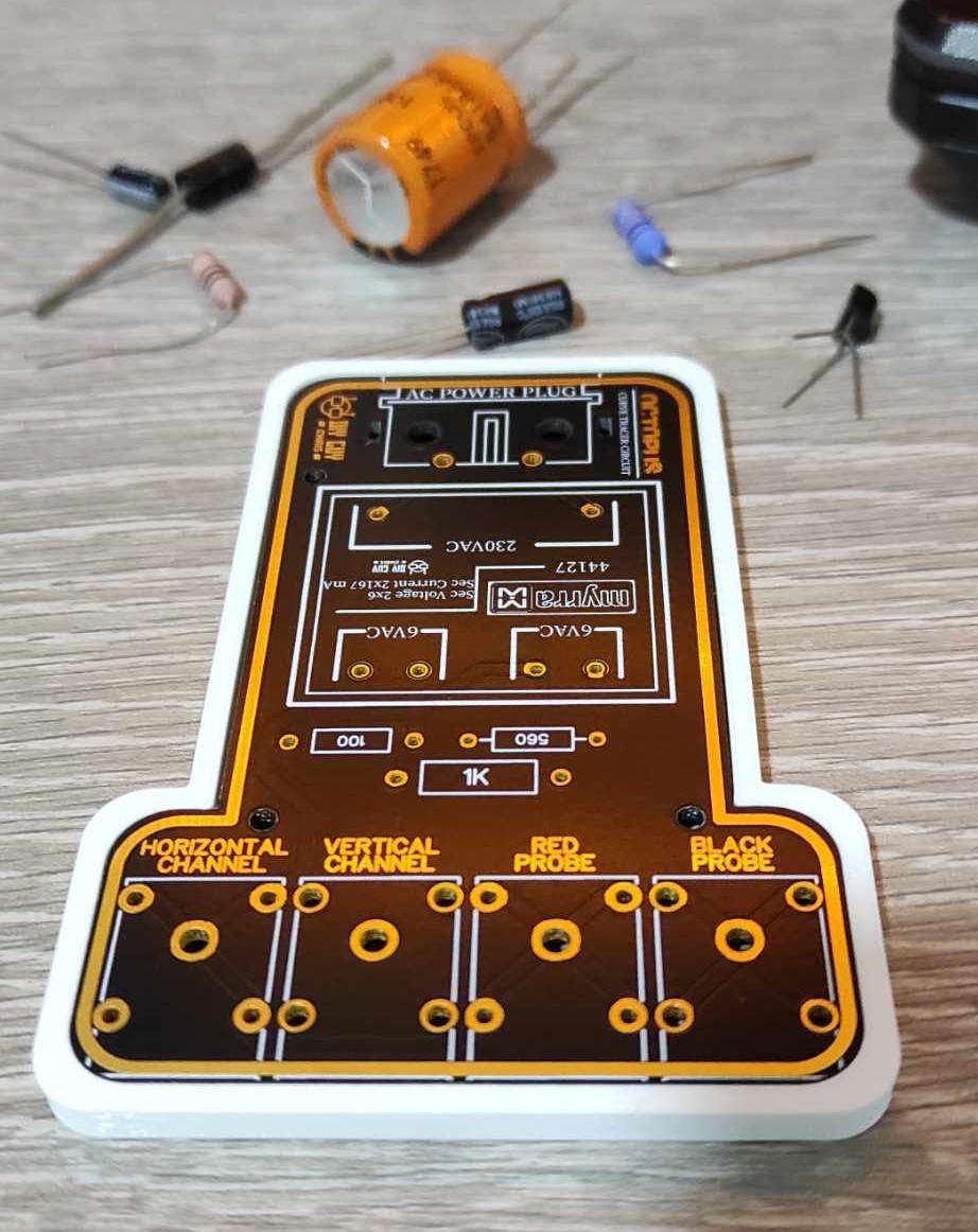
The accuracy of the instrument mostly depends on the resistors R1 to R6, so they should have a tolerance of 1%. In addition, in the video, I will present you testing of several different electronic components. Finally, the device is placed in a suitable box and is an indispensable accessory in your lab.