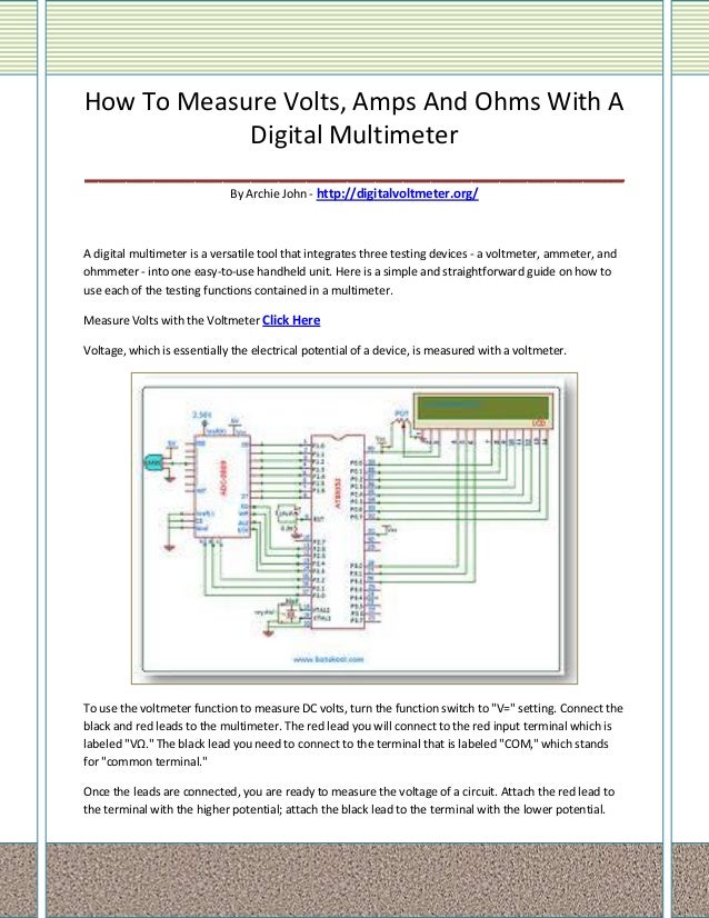
Digital voltmeter Circuit Diagram Working of this Digital Voltmeter Circuit is very simple. ADC inside the IC is integrating converter or Dual type Analog to digital converter. I have same design ckt of volt meter but the problem be is when I calibrate 5v =12.00 v the the meter reading will changes 0.10 v & it will slowly decresing reading , it's take 2 to 3 min for showing
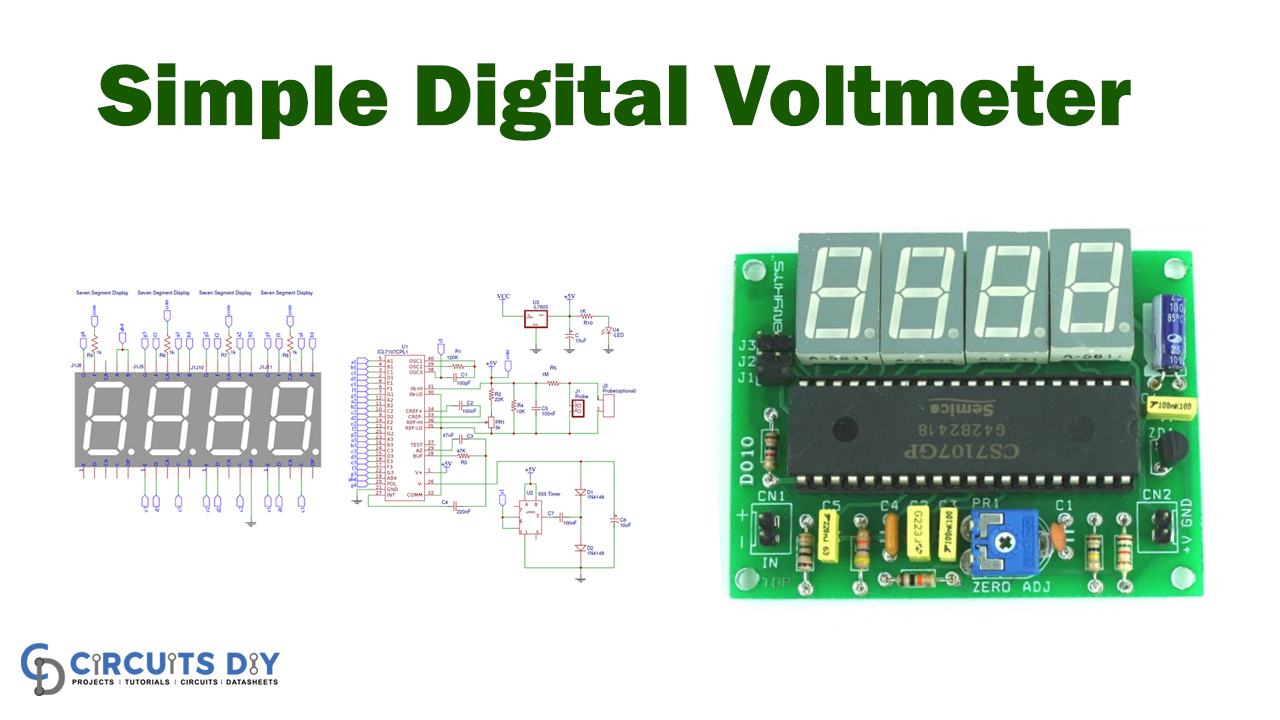
The transistors are BC640, however you may try other transistors like 8550 or 187 etc. The proposed digital voltmeter, ammeter circuit module can be effectively used with a power supply for indicating the voltage and current consumption by the connected load through the attached modules. Referring to the circuit diagram below, the 3 digit digital display module is build through the ICs CA 3162 In this project we have a tendency to design a circuit to build an electronic voltmeter while not making use of any microcontroller. Here we have a tendency to employing a very moderate IC for voltage activity particularly ICL7107/CS7107. Making use of ICL7107, we are able to build correct and really low price digital voltage measurement meter.
25V Digital Voltmeter using AVR Microcontroller Circuit Diagram
But to measure greater levels of voltage, something more is needed. To get an effective voltmeter meter range in excess of 1/2 volt, we'll need to design a circuit allowing only a precise proportion of measured voltage to drop across the meter movement. This will extend the meter movement's range to higher voltages.
1. If you are interested in this circuit. You can apply to The digital capacitor meter project. 2. If you fear that it will not work. You can see the details of… Digital LED Voltmeter Kit. 3. You can look at the digital multimeter using ICL7107. 4. In the past, I used an old digital voltmeter circuit. But it was very old. You may not be able

Electronics Textbook Circuit Diagram
In a digital voltmeter, the analog voltage is converted into a digital value and displayed on a digital screen, making it easier to read and interpret. To start building your digital voltmeter circuit, you will need a few basic components, including an analog-to-digital converter (ADC), a microcontroller, a voltage reference, and a display.
