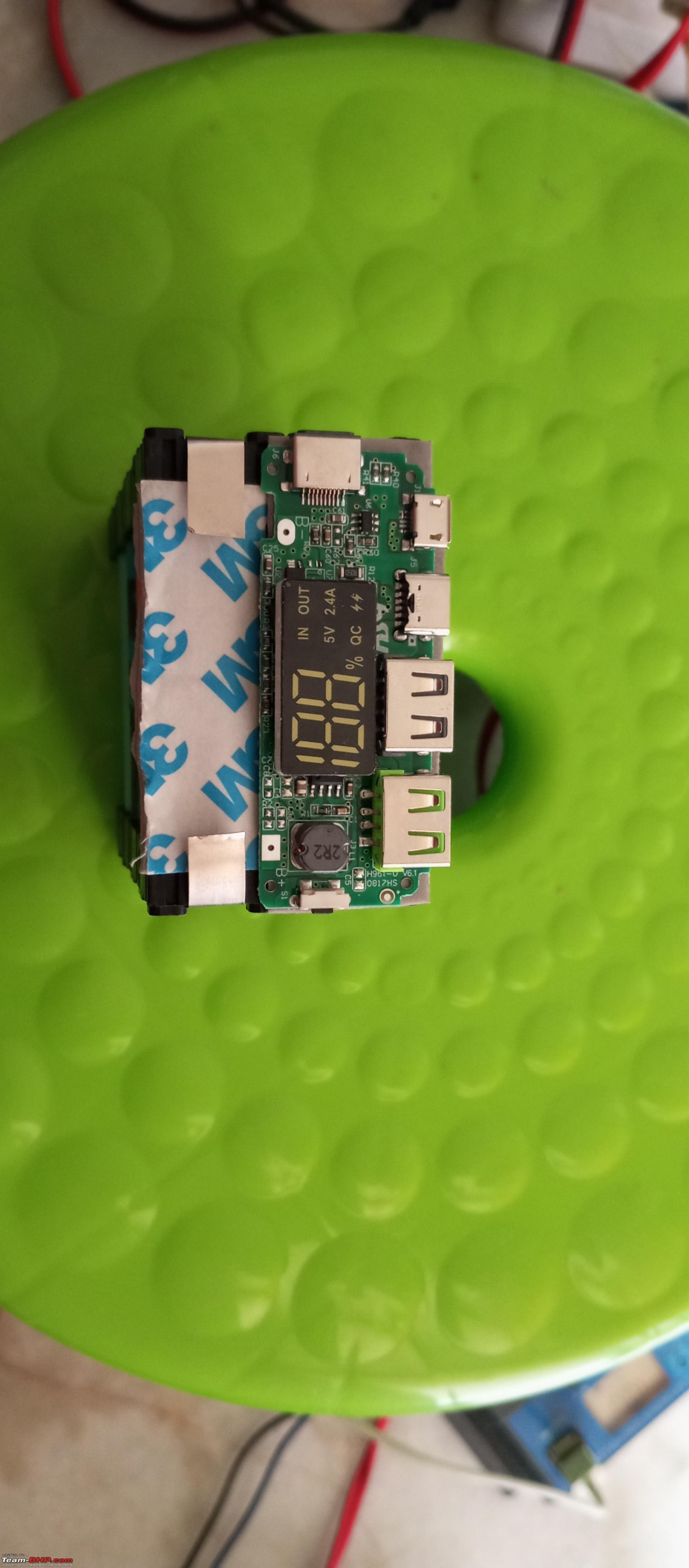
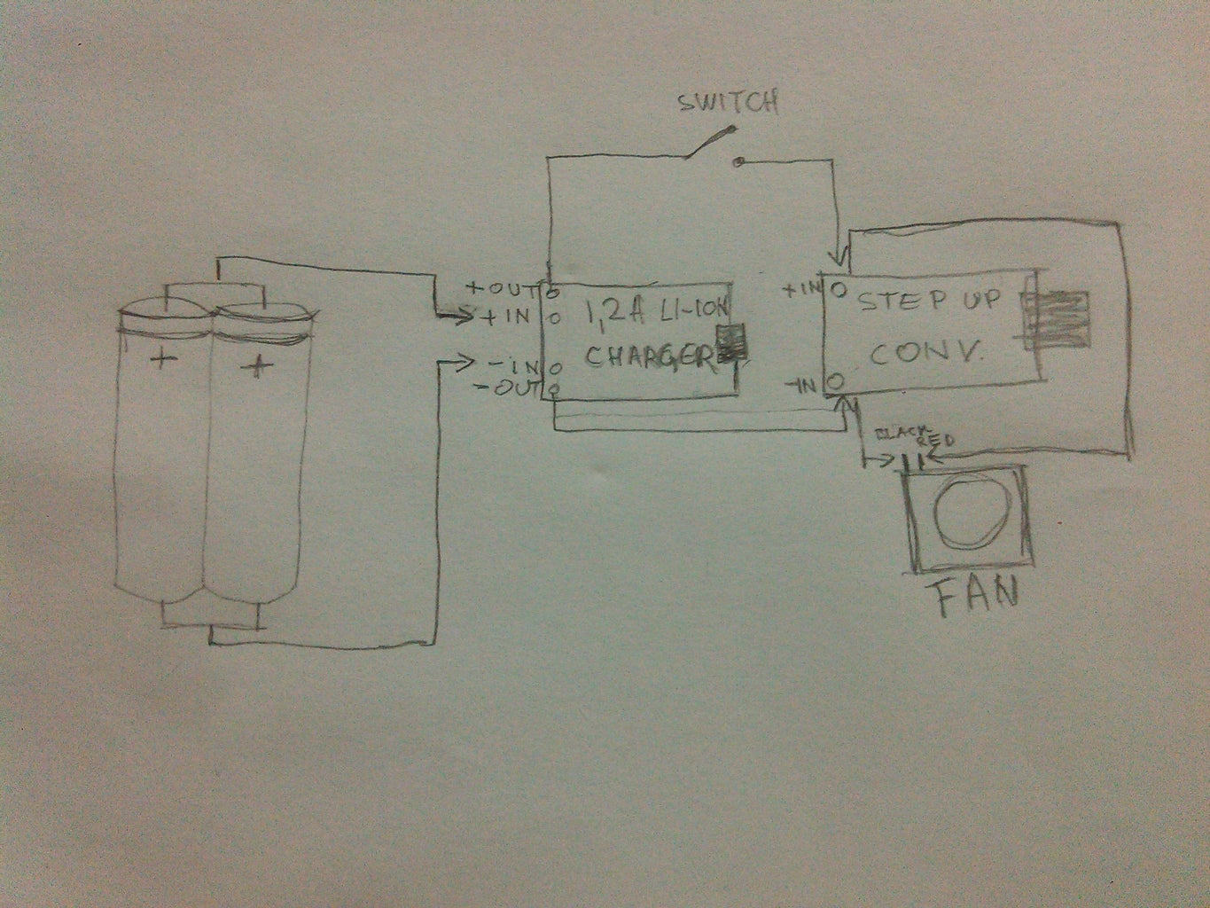
Does anybody know how i can make it so when usb is connected it Circuit Diagram In this small project I will show you how to create a DIY USB Type-C PD powerbank the super simple way. To do that I will firstly test a powerbank PCB based around the IP5328P IC I got from Aliexpress. The measurements will show us how suitable the PCB is for creating a DIY powerbank. Power Bank circuit using a single USB output port compact module: In this circuit we will use a compact module, it comes with a USB 5volt 1A rating. It is used where only one USB output is sufficient for use, also saves space as it is very compact. The major advantage for this module is that it restricts simultaneous charging and discharging of When building a DIY power bank with USB ports, you can go about powering the USB charge portion of the circuit one of two ways. You can either raise the voltage of a single lithium-ion cell or cell group up to 5 volts, or you can lower a higher battery pack voltage down to 5 volts.

The following components are required to make Power Bank Circuit. First place and solder the female USB port and 12DC input pin on the Vero board. Now, connect a resistance of 1K in a way that one end is connected to a 12V pin and one end to the positive pin of the LED. Connect the negative of an LED to a 12V negative pin.
DIY USB Power Bank Circuit Diagram
This DIY USB Power Bank packs 18650 battery cells and a power management board into a 3D printed case. The four cells provide 16,000 mAh, which should give you a few charges. Here is simple circuit to keep your USB Power Bank active "awake" so it stops automatically shutting off. Click the SHOW MORE tab below for links. *Building
The power is stored in a power ban by charging and it can be used when you need, In any power bank, A battery or combination of some small special batteries (cells) used to produce the power source to provide for mobile or other electronic gadgets battery charging. The USB port is used to input for charging and also for output. It has a circuit The image shows the pin configuration of USB socket. I soldered the USB onto a piece of pref-board and connected the wires coming from the boost converter. I also connected two Blue LEDS in parallel to the Output and it turns ON whenever the power bank is active. The circuit diagram is in the pictures attached above.

7 Simple Power Bank circuits using TP4056 & 18650 battery Circuit Diagram
DIY Power Bank ?: Before Starting if you bored of reading you can check out my YouTube Channel for Full video tutorial. Step 3: Making the Circuit. 1) Connect the cathode of battery to -ve terminal of TP-4056 and the step up module. And at the end connect output of step up module to USB port. Now you can charge your Mobile but