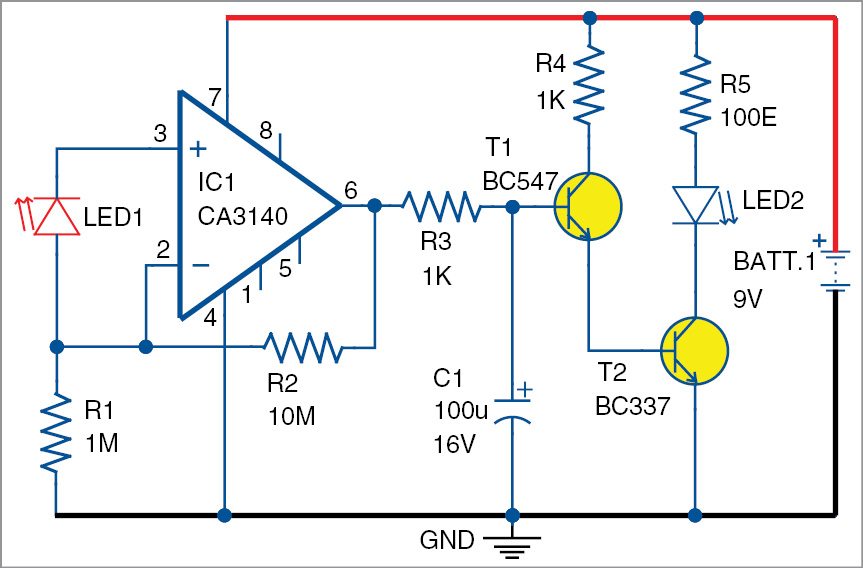
Electronics Do It Yourself Project Circuit Diagram A tutorial on How to make a Light sensor circuit and Darkness detector circuit using LDR and transistor, along with detailed explanation on how the circuit w In the Dark Sensor Circuit (second diagram) when the LDR's resistance decreases when the intensity of light increases. So the voltage at the base of transistor increases when the brightness of light decreases, and once it gets past the minimum threshold voltage required at the base of transistor, it turns on the LED.
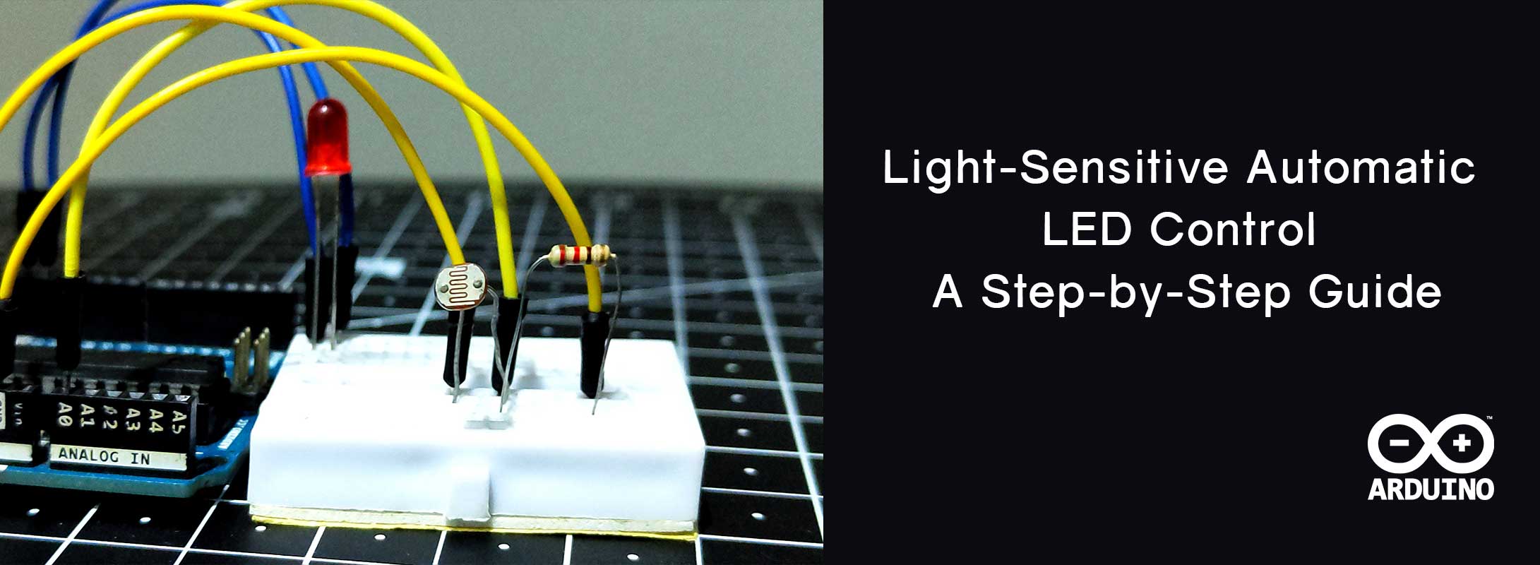
If the light is bright, its resistance is lower while if the light is darker the resistance is higher. Potentiometer: The potentiometer is used to adjust the sensitivity of the circuit. By turning the knob, you can change the resistance, which changes the point at which the LED will turn on or off based off the light detected by the LDR. Resistors: Connecting a Light Sensor to an Arduino. To connect a light sensor to an Arduino, connect the light sensor in series with a resistor between 5V and GND. Then connect the middle point between the resistor and light sensor to an analog input pin on the Arduino. This setup works with photoresistors, photodiodes, and phototransistors. Learn how to use light sensor to control LED. The detail instruction, code, wiring diagram, video tutorial, line-by-line code explanation are provided to help you quickly get started with Arduino. Howerver, please do not copy the content to share on other websites. We took a lot of time and effort to create the content of this tutorial

Easy to Make LED Light Sensor : 5 Steps Circuit Diagram
In this guide, we'll create a circuit where an LED lights up in the dark using a PNP transistor. How It Works. The circuit uses a Light Dependent Resistor (LDR) to detect light levels and a PNP transistor to control the LED. The LDR and a resistor form a voltage divider, which determines the voltage at the transistor's base.
In this tutorial we'll learn how to make a light sensor circuit using LDR (Light Dependent Resistor), 555 timer IC and a few other electronics components. This circuit detects light incident on the LDR and turns on LED whenever the intensity of light is greater than a certain level.
Arduino-Controlled Light-Sensitive LED Circuit Circuit Diagram
Explore comprehensive documentation for the Arduino-Controlled Light-Sensitive LED Circuit project, including components, wiring, and code. This project features an Arduino UNO-based circuit that adjusts the brightness of an LED in response to ambient light levels detected by a photocell (LDR). A 10K resistor forms a voltage divider with the LDR to provide an analog input to the Arduino, which