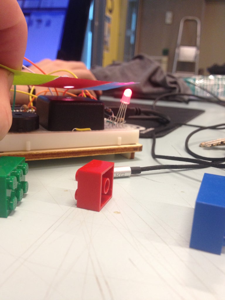
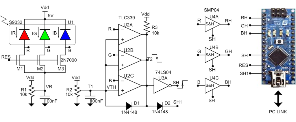
Everything You Need to Know About Colour Sensors 9 Steps Circuit Diagram DIY Color Sensor: Arduino-based proof of concept for a simple, DIY color sensor using an RGB LED. It is a two-terminal electronic component that conducts current primarily in one direction. It has low (ideally zero) resistance in one direction, and high (ideally infinite) resistance in the other. Construct the circuit as shown in the For this project, we will use the TCS230 color sensor and the color will be displayed on the ST7735 1.8″ TFT Display. The TCS230 is a programmable color light-to-frequency converter which combines configurable silicon photodiodes and a current-to-frequency converter on a single monolithic CMOS integrated circuit. TCS230 Color Sensor Step 3: Build the Circuit. and enjoy the color changing light show. The sketch doesn't do much, it just updates the background with the colour being sent out from the sensor. Make sure that you set the com Port correctly. In the pictures, you can see me scanning each side of a four coloured juggling ball, and the output on the screen.

The TCS 3200 Color Sensor comes in the form of a Module with all the components like header pins, 4 White LEDs, Resistors and Capacitors in addition to the Actual TCS 3200 Color Sensor. The following image shows the real time Color Sensor Module. Working of the Project. A simple Color Sensor using Arduino is developed in this project. Recently, I've used this sensor to make a Chameleon lamp. This lamp uses a color sensor to sense the color of it's base and replicate it using RGB LEDs. It is interesting to see how simple and cheap electronics can be used to make something unusual. And the lamp worked quite well ( unexpectedly though :D ) Test 2: Output the color instead of RGB values Here in the code 2, we don't display the values, but the color of the object if identified, here we have green object and green is detected. Test 3: RGB LED to reproduce the color detected Code 3, the blue color of the notebook is reproduced with the RGB LED Add-ons

DIY Color Sensor : 8 Steps (with Pictures) Circuit Diagram
Throughout our exploration of the sensor, we can clearly see its potential application in both industrial and arty ways. Firstly, the sensors are good at distinguishing which color is present (as you would expect), but we haven't been able to get good absolute RGB from the sensor (as in, point a 0,255,0 coloured object at it, it won't give 0,255,0).

A color sensor is a device that can detect and differentiate between certain primary colors. The sensor we will use in this circuit is a TCS3200 color sensor. This sensor can detect and differentiate between the colors white, blue, green, and red. A color sensor is actually a very useful device. Written instructions for this color detection circuit science project, including a parts list and circuit diagram, are available on the Science Buddies websi

Using an RGB LED to Detect Colours Circuit Diagram
1 /* This code works with GY-31 TCS3200 TCS230 color sensor module 2 * It select a photodiode set and read its value (Red Set/Blue set/Green set) and displays it on the Serial monitor 3 * and identify if possible the color 4 * Refer to www.surtrtech.com for more details 5 */ 6 7 #define s0 8 //Module pins wiring 8 #define s1 9 9 #define s2 10
