Filter circuits Circuit Diagram This then makes this type of circuit ideal for converting one type of electronic signal to another for use in wave-generating or wave-shaping circuits. The purpose of the tutorial is to educate and learn to design filter circuits, not just copy. For selectivity and high Q values, high-order Active Bandpass Filters are preferred. Posted
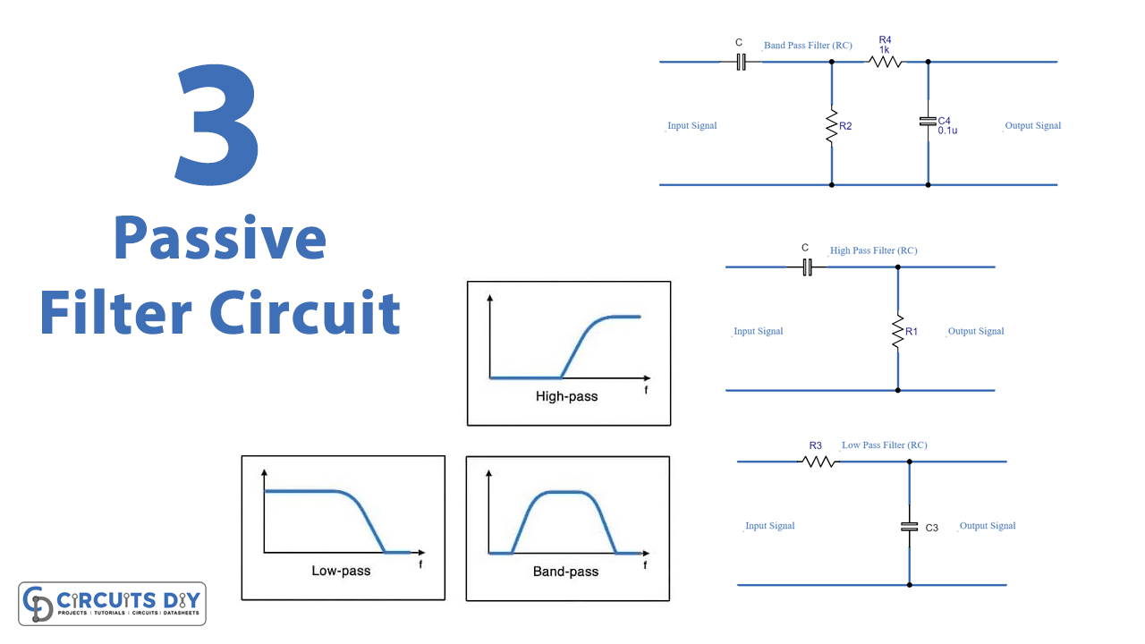
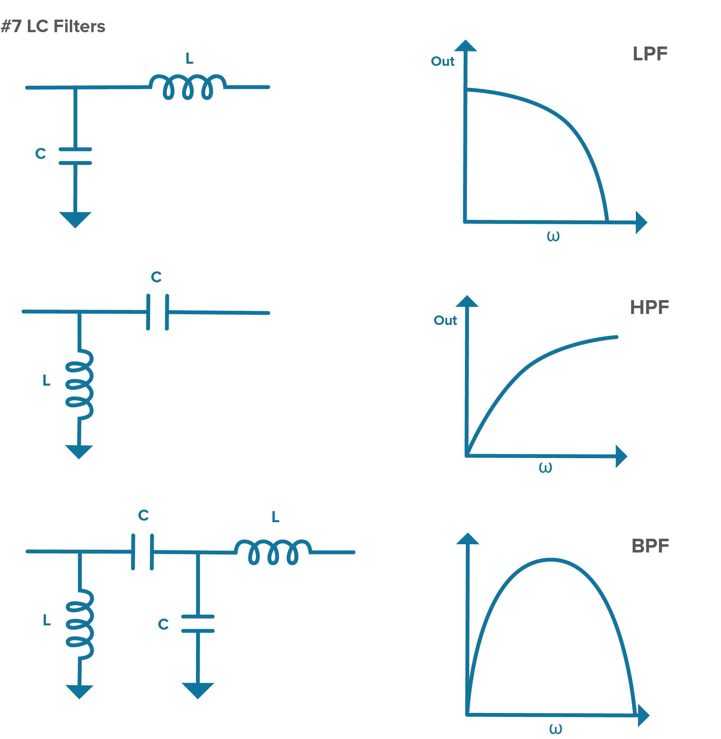
The most basic electronic filter is a filter RC circuit. Filter RC circuits can act as a low pass filter or high pass filter. The terms of low and high frequencies do not have specific values prior to designing a circuit. The real value of low and high frequencies are determined by our "how to design a filter circuit".
An Introduction to Filters Circuit Diagram
limitations of active elements (op amps) in filters 8.114 distortion resulting from input capacitance modulation 8.115 q peaking and q enhansement 8.117 section 8.8: design examples 8.121 antialiasing filter 8.121 transformations 8.128 cd reconstruction filter 8.134 digitally programmable state variable filter 8.137 60 hz. It is therefore in the interest of anyone involved in electronic circuit design to have the ability to develop filter circuits capable of meeting a given set of specifications. Unfortunately, many in the electronics field are uncomfortable with the subject, whether due to a lack of familiarity with it, or a reluctance to grapple with the
Electronic filters are a type of signal processing filter in the form of electrical circuits. This article covers those filters consisting of lumped electronic components, The oldest designs are simple circuits where the main design criterion was the Q factor of the circuit. This reflected the radio receiver application of filtering as Q
PDF Basic Introduction to Filters Circuit Diagram
involved in electronic circuit design to have the ability to develop filter circuits capable of meeting a given set of specifications. Unfortunately, many in the electronics field are uncomfortable with the subject, whether due to a lack of familiarity with it, or a reluctance to grapple with the mathe-matics involved in a complex filter design.

Active filters are capable of dealing with very low frequencies (approaching 0 Hz), and they can provide voltage gain (passive filters cannot). Active filters can be used to design high-order filters without the use of inductors; this is important because inductors are problematic in the context of integrated-circuit manufacturing techniques.
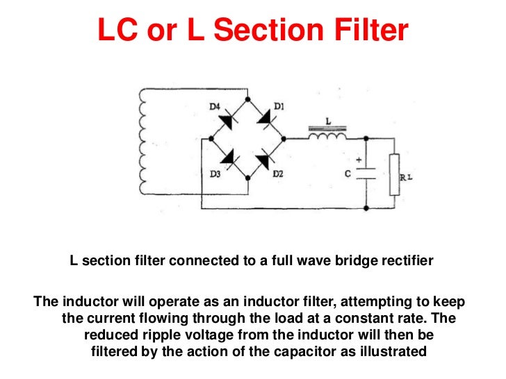
Types of Filter Circuits: Working Principles, Formula & Applications Circuit Diagram
volved in electronic circuit design to have the ability to develop filter circuits capable of meeting a given set of specifications. Unfortunately, many in the electronics field are uncomfortable with the subject, whether due to a lack of familiarity with it, or a reluctance to grapple with the mathematics involved in a complex filter design.