Force Measurement with a Strain Circuit Diagram The measure of resistance determines the strain applied. Measurement of Strain Using Strain Gauge : The strain gauge can be used in different possible arrangements for measuring strain. They are, In this first arrangement, a single strain gauge SG 1 is fixed on the elastic member (which is under test) as shown below. Here the strain gauge Before wiring the strain gauges, make sure that it has a resistance of ~120Ω. For the 3-wire gauges, measure the resistance from the red to each of the other leads. If is the R<<120Ω or R>>120Ω, the strain gauge is probably broken. If so, please inform an instructor & get a different assembly. Check your strain gauge for mechanical integrity.
The strain gage measures force indirectly by measuring the deflection it produces in a calibrated carrier. Pressure can be converted into a force using an appropriate transducer, and strain gage techniques can then be used to measure pressure. Flow rates can be measured using differential pressure measurements which also make use of strain gage By using two strain gauges in the bridge, the effect of temperature can be avoided. For example, Figure 5 illustrates a strain gauge configuration where one gauge is active (R G + ∆R), and a second gauge is placed transverse to the applied strain. Therefore, the strain has little effect on the second gauge, called the dummy gauge.
PDF SECTION 4 STRAIN, FORCE, PRESSURE, AND FLOW MEASUREMENTS Circuit Diagram
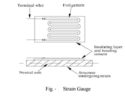
A strain gauge is designed to measure the strain amount by using the principle that the resistance changes with the expansion/contraction of the strain gauge. to polish an area slightly wider than the strain gauge. Using clean cloth (or something similar) soaked with acetone, degrease and clean the polished surface until the cloth does not Stress is a measurement of the force applied divided by the initial cross-sectional area of an object, or the internal resisting capacity of an object. Figure 1. Left: Composition of a strain gauge Torque vs. Time testing measurements using a strain gauge. Conclusion. measure the strain on individual members of a structure or machine. Then we use the stress-strain relationships to compute the stresses in those members to verify that these stresses remain within the allowable limits for the particular materials used. STRAIN When a force is applied to a body, the body deforms. In the general case, this

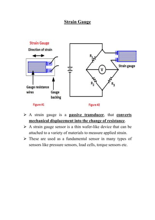
Key learnings: Strain Gauge Definition: A strain gauge is a device that measures the deformation (strain) of an object when force is applied, through changes in electrical resistance.; Working Principle: The strain gauge detects minute geometrical changes as resistance changes, which indicate the level of stress on the material.; Bridge Circuit: The strain gauge is part of a bridge circuit
PDF Practical Strain Gage Measurements Circuit Diagram
Sensors & Transducers | Measurement of Force Using Strain Gauges |