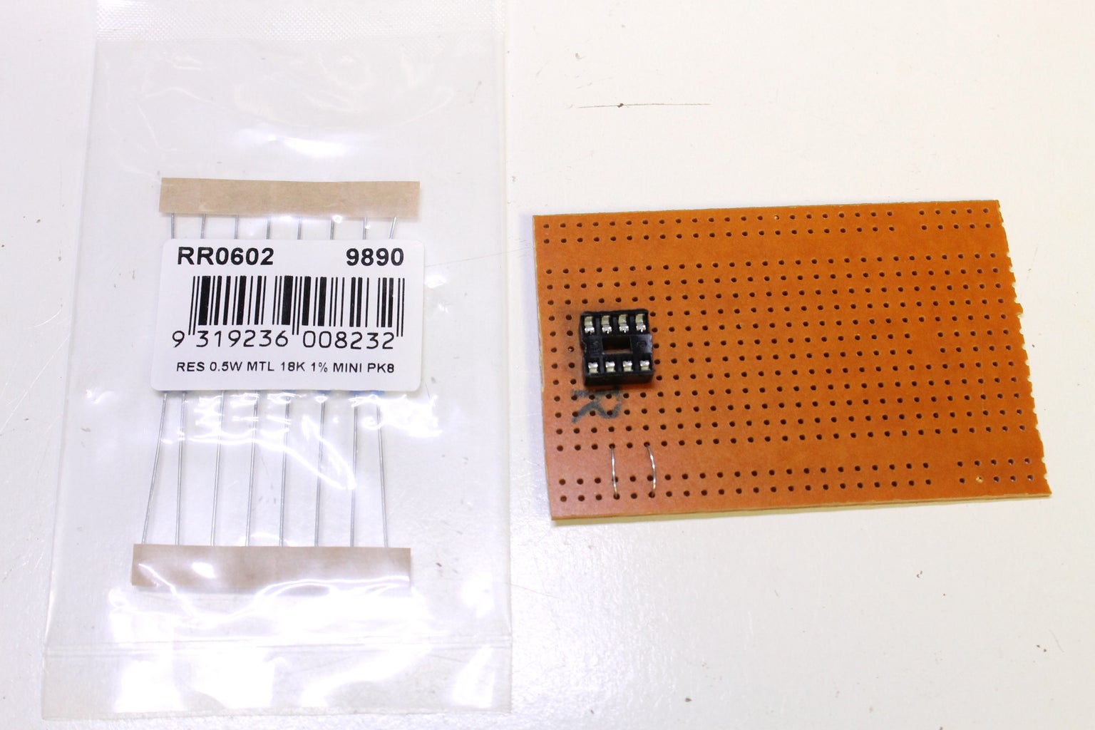
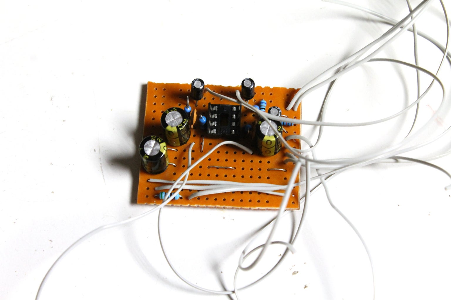
How to build Headphone Class A Amplifier Circuit Diagram The circuit diagram of the LM4910 stereo headphone amplifier is witnessed above. C1 and C2 are actually the input DC decoupling capacitors for the left together with right input channels. R1 along with R2 tend to be the individual input resistors. R3 is the feed back resistor for left channel whereas R4 is the feed back resistor for the right The circuit board is heated from underneath until temperature is high enough to melt the solder and reflow the components. Cooling the board is difficult to control. and the capacitors create high-pass filters, reducing amplifier gain at DC to unity. This filter also has 16 Hz corner frequency. A new headphone amp is ready. Filed Under This is a headphone amplifier similiar to the one designed by Chu Moy. For reference, the original Chu Moy article is here while a great tutorial on building it is here.I have used a different dual operational amplifier, the RC4560, manufactured by Texas Instruments, in the TSSOP package, and chip resistors in order to make an extremely small printed circuit board assembly.
Learn how to design audio circuits, This tutorial will show you how to connect a 3.5 mm audio jack from an old pair of headphones to the audio input of your DIY audio projects. Learn how to build eight different op-amp circuits, including an inverting and non-inverting amplifier, voltage follower, differential amplifier, integrator
Building your own headphone amp: a detailed schematic Circuit Diagram
Diy Headphone Amp Schematic: A Guide to Building Your Own. Building your own headphone amp can be a rewarding and cost-effective project for audio enthusiasts. By following a diy headphone amp schematic, you can customize the amp to your preferences and create a high-quality sound reproduction system for your headphones.
I test this circuit using my Sennheiser HD201 headphones, they are quite efficient and sound pretty tasty with this circuit! :P It only uses a handful of components which most electronics builders can find in their component boxes etc. This circuit can work on any voltage from 6v-24v aslong as heatsinking the components is taken into consideration. A headphone amplifier is a relatively low-power amplifier that boosts the low-voltage audio signal from a source device (be it a turntable, laptop, or smartphone) to a sufficient level, such that it converts (or transduces) into sound waves by the speakers inside your headphones. It works like the amps which power full-sized speakers but also operate at a lower scale. The NE5532 headphone amp schematic typically includes the NE5532 op-amp, resistors, capacitors, and other components that are required to create the amplifier circuit. It may also include additional features such as volume control, input and output buffers, and power supply regulation to enhance the performance of the headphone amplifier.

Make a Headphone Amp V2 : 10 Steps (with Pictures) Circuit Diagram
Typically, a headphone is connected to the loudspeaker output of the final amplifier stages through a voltage divider circuit. However, this simple design has two distinct disadvantages. Firstly, the headphone volume cannot be varied independently from the main speaker when the main speaker is switched on at the same time.