How To Check Gyroscope Sensor In Android Mobile Circuit Diagram 3-Axis Gyroscope. MPU6050 has a 3-axis gyroscope that uses Micro Electro Mechanical System technology to measure rotational velocity. The gyroscope consists of a tiny mass that moves back and forth in response to rotational motion. As the mass moves, it causes a change in capacitance, which is detected by the MEMS sensors.

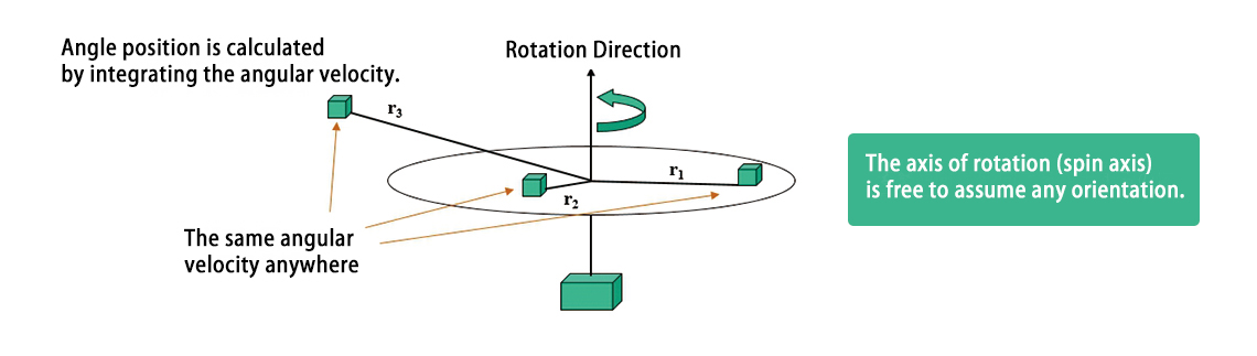
The MPU-6050 IMU (Inertial Measurement Unit) is a 3-axis accelerometer and 3-axis gyroscope sensor. The accelerometer measures the gravitational acceleration, and the gyroscope measures the rotational velocity. Additionally, this module also measures temperature. This sensor is ideal for determining the orientation of a moving object.

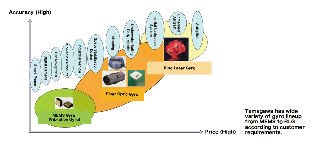
Gyroscope Sensors: Types, Working, and Real Circuit Diagram
Using the ESP32 & BMI160 Accelerometer and Gyroscope Module, we can develop a C++ Code to read the Acceleration values. We have converted the raw readings into acceleration using the mathematical equations. The following code initializes the BMI160 sensor using I2C communication. It sets the accelerometer to normal mode.
Three Axis gyroscope sensors are very useful in making like flight controllers, ship/boat controllers, direction prediction and controlling the Microcontroller accordingly. In today's tutorial, we will discuss about MPU6050 gyro sensor and make a small project to know the functionality. Which can show Pitch, yaw and roll readings on display.
Using Gyroscopes to Enhance Motion Detection Circuit Diagram
So, if we fuse, or combine the accelerometer and gyroscope data we can get very accurate information about the sensor orientation. The MPU6050 IMU is also called six-axis motion tracking device or 6 DoF (six Degrees of Freedom) device, because of its 6 outputs, or the 3 accelerometer outputs and the 3 gyroscope outputs.
