How to make a power switch using MOSFETs Circuit Diagram When using the MOSFET as a switch, it is critical that the device has a low R DS(on) channel resistance that is proportional to the input gate voltage. Looking at the above image, we configured two MOSFETs to create a bi-directional switch utilizing a dual power supply. In this setup, the motor is connected between the common drain point In this project, we will go over how to connect an N-Channel MOSFET to a circuit for it to function as an electronic switch. The type of N-Channel MOSFET we will use is the enhancement-type MOSFET, the most commonly used type of MOSFET. MOSFETs, like BJTs, can function as electronic switches. Although unlike BJTs, MOSFETs are turned on, not by

In broad strokes, a MOSFET device allows us to use a relatively low voltage at the gate to modulate current flow from drain to source. Two basic types of MOSFETs are bought as discrete devices objective is to help the system designer understand how to use these devices correctly and avoid common mistakes, thereby reducing design time. A list of useful references is provided at the end for more in-depth study. Intended audience Power engineers and students designing with power MOSFETs. This is intended for engineers with a basic The operation of the enhancement-mode MOSFET, or e-MOSFET, can best be described using its I-V characteristics curves shown below. When the input voltage, ( V IN) to the gate of the transistor is zero, the MOSFET conducts virtually no current and the output voltage ( V OUT) is equal to the supply voltage V DD.So the MOSFET is "OFF" operating within its "cut-off" region.

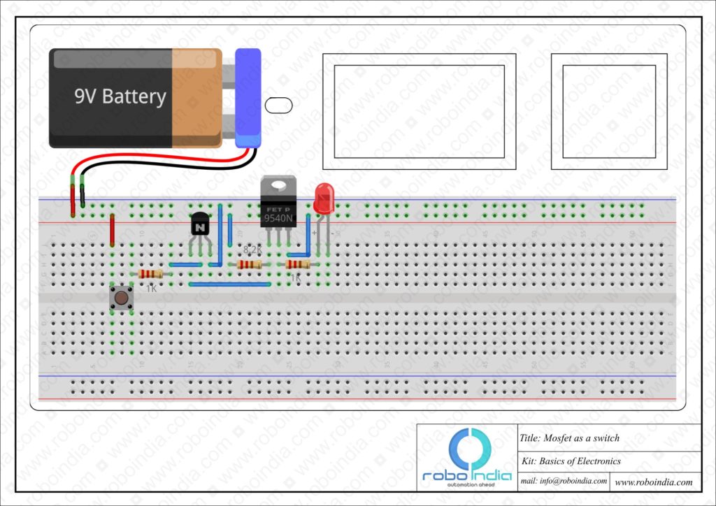
Electronics Tutorial Circuit Diagram
MOSFETs exhibit high input impedance, making them versatile and adaptable to various applications. How to Use MOSFET as a Switch. To use a MOSFET as a switch, you need to ensure that the gate-source voltage (Vgs) is higher than the source voltage. When the gate is connected to the source (Vgs=0), the MOSFET remains off.

In most cases, you can use the same power supply that you are using for your high power device to operate the MOSFET as well, using a mechanical switch to apply the gate voltage. The image below shows exactly that type of application. (Alternatively, you can also use an electronic signal, like from a microcontroller, to activate the MOSFET When the gate voltage is lower than the threshold no such channel exists and the switch is considered as open. Two types of MOSFET devices can be identified. The n-channel MOSFET shortly NMOS and p-channel MOSFET shortly PMOS. The NMOS transistor contains n+ drain and source regions which are placed on p-type substrate as shown in Figure. Semiconductor switching in electronic circuit is one of the important aspects. A semiconductor device like a BJT or a MOSFET are generally operated as switches i.e., they are either in ON state or in OFF state. Ideal Switch Characteristics. For a semiconductor device, like a MOSFET, to act as an ideal switch, it must have the following features: