Making a Volume Control for your PC Circuit Diagram In order to make sure that audio levels remain consistent, automatic volume control circuit diagrams provide a simple and efficient way to address this issue. With an AVC circuit diagram, devices can adjust the volume level of sound output without needing manual input.
Building a volume controller circuit is a simple yet essential skill for anyone interested in audio electronics. By understanding the basic components, types of potentiometers, and the step-by-step construction process, you can create your own volume controller and incorporate it into your audio projects. The digital volume control circuit is a true marvel of engineering. It makes volume control as simple as pressing a button, allowing you to focus on what matters - enjoying the audio. With its reliable and accurate performance, you can indulge in a seamless listening experience without interruptions. This digital volume control has no pot to wear out and introduces almost no noise in the circuit. Instead, the volume is controlled by pressing UP and DOWN buttons. This simple circuit would be a great touch to any home audio project. Schematic: Parts: C1 0.1uf Ceramic Disc Capacitor U1 DS1669 Digital Pot IC (See Notes) S1, S2 Momentary Push

Automatic Volume Control Circuit Diagram
The digital volume control circuit that uses the MAX5486 IC is a great choice for audio projects because it is accurate, efficient and easy to use. It has push button controls and LED lights, which make it simple to adjust the volume whether you want to turn it up, turn it down, mute it, or unmute it. Wiring A Balanced Stereo Passive Volume Control. Digital Volume Control Circuit Eleccircuit Com. Loudspeaker Volume Controls Selector Switches Audio Volt. Esp A Better Volume Control. Avc Automatic Volume Control Circuit. Lm386 Based Stereo Audio Amplifier With Digital Volume Control Embedded Lab. Schematic Diagram Of Air Volume Control Circuit A digital volume control circuit diagram using DS 1669, a potentiometer IC.This can be used as a digital volume controller for audio amplifiers and other applications. Here this project is to create an audio controller that works digitally. This is a very simple project which uses two switches and an IC to electronically control the audio

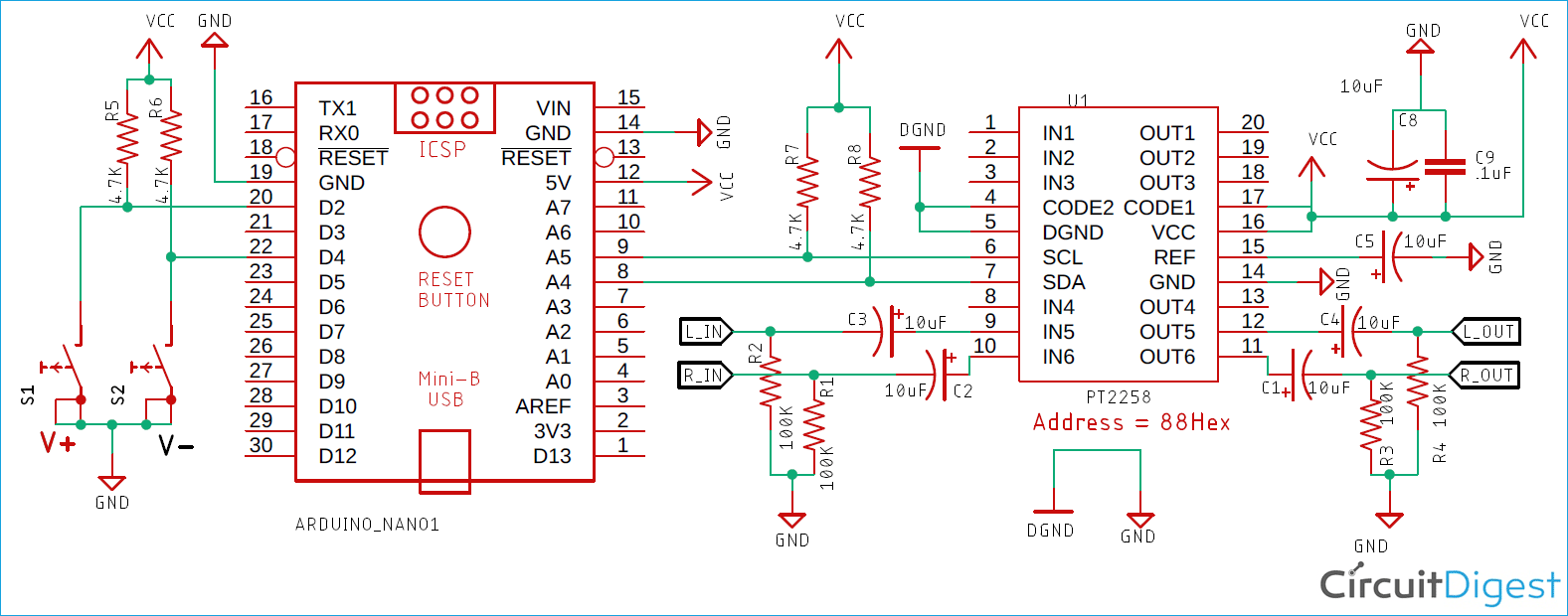
So in this project, I am going to show you how to build your Digital Volume Controller with the IC PT2258 and interface it with an Arduino to control the volume of an amplifier circuit. You can also check various Audio related circuits here including VU meter, tone control circuit, etc. IC PT2258. As I have mentioned earlier, the PT2258 is an Audio Auto Fade. This circuit is design, in order to is heard the voice above the music. Useful for DJ, for small radio stations, for statements above the music, in shops etc. Simple Digital Volume Control. This digital volume control has no pot to wear out and introduces almost no noise in the circuit. Instead, the volume is controlled by DIY Volume Control Circuit. Making a DIY external volume control circuit can be a very simple and straightforward task. You can choose how difficult you want the project to be by connecting to fewer or more sources. Below, we'll go through the general steps to create your DIY volume control circuit. What You Need . Audio Taper Potentiometer