Photograph of the wind sensor including the PCB used to sample Circuit Diagram The sensor can measure wind speed ranging from 0 to 40 m/s and wind direction from 0 to 360 After assembling the sensor as per the circuit diagram above, lets move to the coding part of this project. According to the above table the inquiry frame for getting the Sensor reading hexadecimal is as follows: 1.

Use an anemometer with the Arduino board to measure wind speed. Power and connect the sensor to the Arduino and write a simple code to get wind speed values in different units. Wiring the Circuit: Arduino with Anemometer.

Raspberry Pi Pico with Anemometer: Measure Wind Speed (Arduino IDE) Circuit Diagram
Use the 3 different colored wires to connect the sensor module. Insert the Hall module and point the sensor facing the magnet at a distance of 2 to 4 mm. Test if the rotation of the shaft does not hit the magnet with the sensor. Use a 3.7 V battery to test if the module responds to the approach of the magnet by turning the led to each contact. Measuring Wind Speed & Testing the Device. Once you upload the code to the Arduino Board, the LCD Display will start displaying the wind speed. When the anemometer cup is stable the LCD will show a speed of around 0m/s. The speed will vary or increase when the sensor is taken in a windy region.

The anemometer sensor we are using here is the Adafruit anemometer. The Adafruit anemometer is capable of measuring wind speeds up to 70 m/s or 156 mph which should be adequate for our location. We can interface the Adafruit Anemometer Sensor with Arduino and OLED Display. The sensor will measure the wind speed in m/s and displays the value on OLED Screen. Connect the sensor to the Pico, and write a simple code to get wind speed values in different units. A voltage divider is a simple circuit that reduces a large voltage into a smaller one. Using 2 resistors and an input voltage, we can create an output voltage that is a fraction of the input. which will correspond to the maximum wind

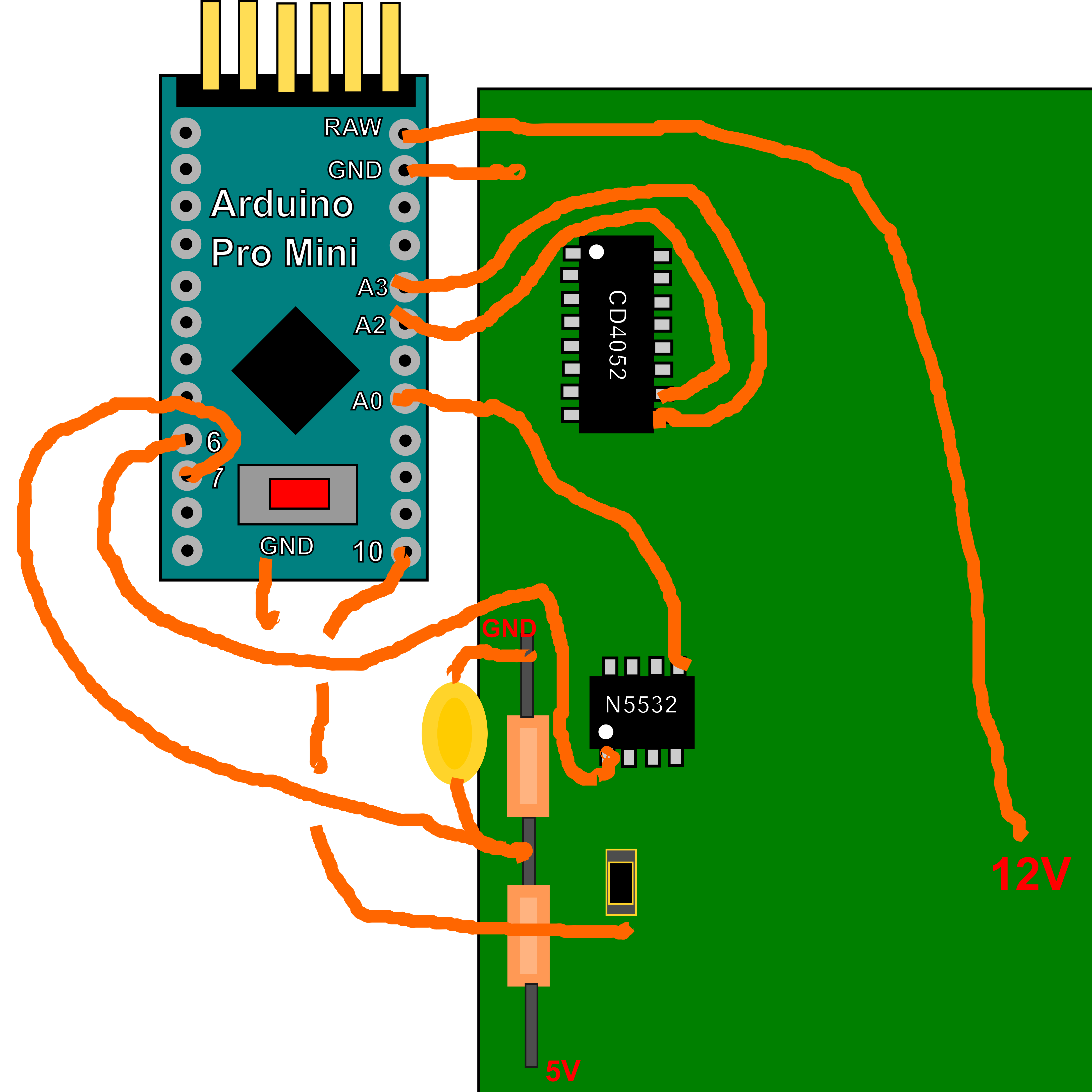
How to Measure Wind Speed using Anemometer & Arduino Circuit Diagram
Introduction: Using an Anemometer and Arduino to Measure Wind Speed. By ForceTronics ForceTronics Store Follow. More by the author: In this Instructable we look at how to measure wind speed using an anemometer and Arduino. This approach will work on both ARM and AVR based Arduinos.
The circuit for the wind speed sensor part is very simple. Since the anemometer (wind speed sensor) might be going to be at the end of about five meters of cable so I used a separate 5VDC power supply and galvanically-isolated it from the Arduino board. The main components are PC817 optocoupler, and of course the hacked fan. Today in this tutorial we will make a Wind Speed Meter Using Anemometer & Arduino and display the wind speed on 0.96 inch OLED Display in m/s. The NPN pulse output Anemometer sensor is a 3 cup type Anemometer that is capable of measuring wind speed up to 70-meter per seconds or 156 mph. It is composed of a shell, the wind cup, and the