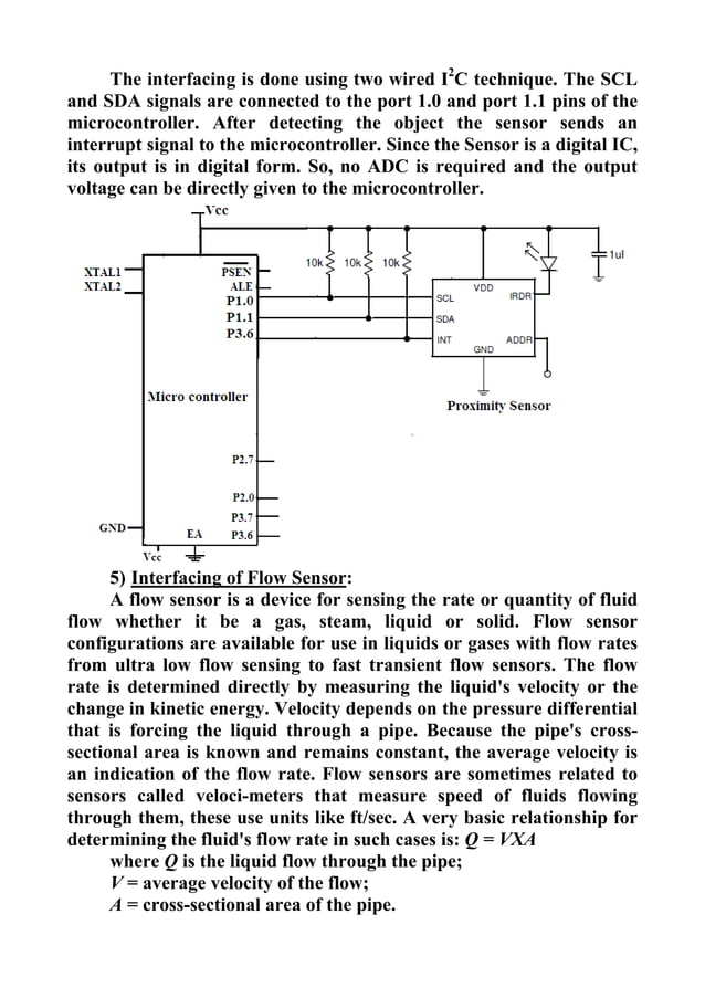
Sensors and microcontroller interfacing Circuit Diagram Select the Appropriate Microcontroller and Sensors. Evaluate the sensor requirements, such as type (e.g., temperature, pressure), communication protocol (e.g., I2C, SPI, UART), and voltage levels. Choose a microcontroller that supports the necessary communication interfaces and has sufficient processing power for the application. Once selected, these devices need to be connected to the microcontroller using various interface protocols like I2C or SPI. Proper wiring techniques ensure reliable communication between the microcontroller and peripherals. Ensure all connections between the microcontroller, sensors, and actuators are secure. Verify that the correct pins
Typically, the bandwidth for temperature sensors is much lower than 50 or 60 Hz so a simple low-pass filter will work well in many cases. Other measures to keep noise away: • Keep the sensor wires short. • Use shielded sensor cables with twisted pair wires. • Use a dedicated precision voltage reference, not the microcontroller supply.

Sensor Interfacing 101: A Comprehensive Guide Circuit Diagram
As an example of direct sensor-to-microcontroller UART usage, this "Large Ultrasonic (Sonar) Sensor with Horn and UART Output" from Adafruit fits the bill. Hook up the red sensor wire to 5V from the Arduino, and black to GND. Connect the yellow control wire to pin 5, and the white wire to pin 2. In my case, I have a fair amount of experience with sensors and Microchip PIC microcontrollers, Arduino-compatible boards, and Raspberry Pi variants. With a protocol-based interface, the sensor and MCU communicate by sending a data stream. In fact, most protocol-based sensors have their own tiny MCU built into the chip or located inside the This article discusses the "ins and outs" of interfacing analog sensors to a microcontroller's analog-to-digital converter (ADC) input pins 1.As shown later in Table 1, a great number of sensors produce a voltage output that varies in response to a change in a physical parameter such as temperature, pressure, or magnetic field intensity.. Voltage output sensors with low output impedance

The microcontroller's input has a high impedance so the changes in the current drawn by the sensor are converted into a measurable voltage by the 250ohm resistor. The value of the 250 ohm resistor is determined using the sensors maximum current 20mA and the micro-controllers maximum input voltage which if Vcc at 5v for the Arduino.
How to Integrate Microcontrollers with External Sensors Circuit Diagram
In simple terms, sensor interfacing is the process of connecting sensors to microcontrollers or other processing systems. This allows microcontrollers to acquire, process, and respond to sensor data, facilitating real-time environmental interaction. This interface enables microcontrollers to: Acquire the signals from sensors The microcontroller communicates with the sensors and actuators to acquire data or trigger actions based on the input received. The interfacing process involves the following steps: Identify the Sensor or Actuator: Determine the type and specifications of the sensor or actuator you want to interface with. Common examples include temperature
