SOLUTION Electric circuit analysis Circuit Diagram We will use three physical quantities in our analysis of electrical circuits: current, voltage, and resistance. Current is the flow of electrical charge from one place to another. Electrons flowing through a wire or through some other electronic device comprise a current. In an electrical circuit, one node is usually chosen as a reference

Now, what is circuit analysis? It is the mathematical analysis of an electrical or electronic circuit. It is the process of studying and analyzing electrical quantities through calculations. By this analysis, we can find the unknown elements of a circuit, such as voltage, current, resistance, impedance, power, among others, across its component. Circuit analysis plays a pivotal role in various fields, including electrical engineering, electronics, telecommunications, and even biomedical engineering. It empowers engineers and scientists to design, troubleshoot, and optimize electrical circuits for a wide array of applications, from simple household appliances to complex communication

How to Circuit Analysis 101 Circuit Diagram
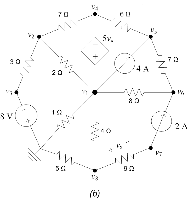
Basic DC electrical circuit analysis. Basic DC circuit analyses techniques, basic electronic devices and their applications. Electronic device recognition and their common functions on printed circuit boards - a pictorial tour. Appendix A . Solutions for self-assessment problems . Appendix B . Common units and unit conversion factors . Appendix C Case 1: If a voltage source is connected between the reference node and a non-reference node, set the voltage at the non-reference node equal to the voltage of the voltage source. In the circuit below, for example,. Analysis is somewhat simplified by this knowledge of the voltage at this node. Case 2: If the voltage source (dependent/independent) is connected between two non-reference nodes

Learn the basics and fundamentals of electrical circuit analysis, such as Ohm's Law, Kirchhoff's Laws, nodal voltage, and mesh current. Find out how to apply them to solve DC and AC circuits, and how to use advanced techniques such as Thevenin and Norton. Circuit theory is the cornerstone of electrical engineering, providing the rules and methods for analyzing electrical circuits. This page delves into the principles of circuit analysis, including Kirchhoff's laws, Thevenin's theorem, and Norton's theorem.
Engineering LibreTexts Circuit Diagram
Learn the basics of electrical circuit analysis, transient response, three phase circuits, locus diagrams and network parameters. Download the lecture notes prepared by Karimulla Peerla Shaiq, Associate Professor of EEE at MRCET.