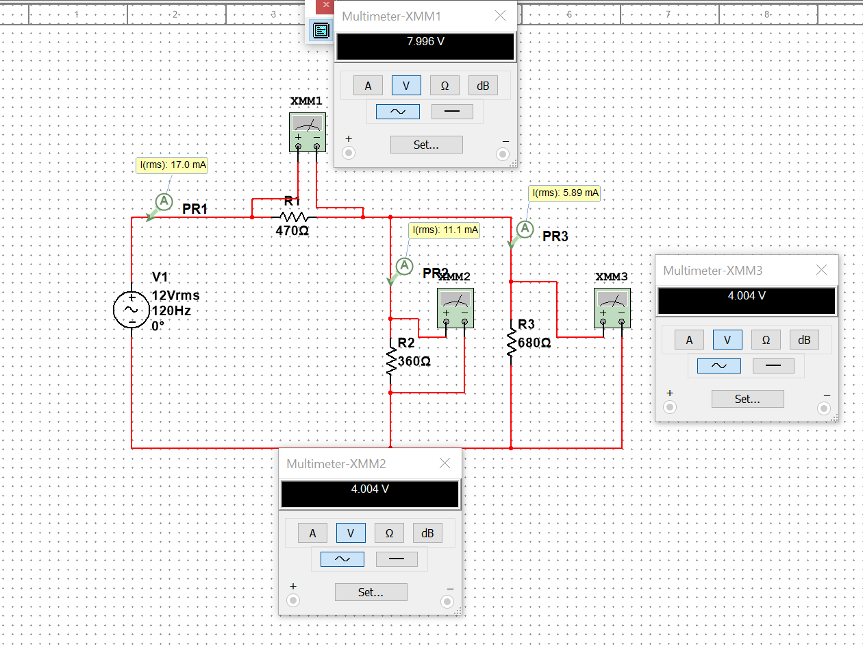
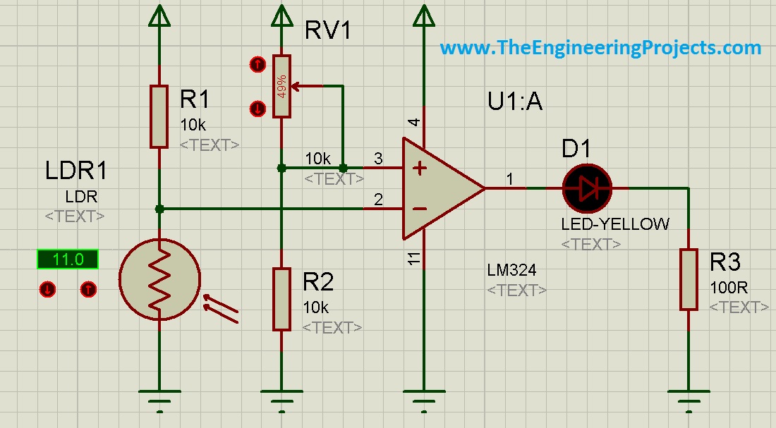
Solved simulate this circuit in proteus software and Circuit Diagram Circuit Simulation using Proteus Professional is a course which is best suited for all electronics and communication or Electronics and Electrical engineers. In this course, you will be able to learn about the basics of Power Supply Design, Component Selection, Component behavior and Electronic component output based on the applications.

Essential Circuit Analysis Using Proteus is a new course work book published by Springer with modules for digital logic and power electronics amongst others. integrated and easy to use suite of tools for professional PCB Design. PCB Design Software. Proteus Circuit Simulation.

Tutorial 1 for Beginners - CoCoClip.AI Circuit Diagram
When you launch Prteus click on New Project or press CTRL+N. A new window called New Project Wizard appears. Start; There you can change the Name and Path of the project after setting click Next. Schematic Design; Now you need to Mark Create a schematic from the selected template then you can either select Default or you can select any templates size normally we select landscape A4, by Proteus software installed on your computer (you can download it from the official Labcenter Electronics website). Basic knowledge of electronic components, circuit theory, and schematic symbols. A clear understanding of the circuit you want to design and its requirements. Step 1: Creating a New Project. Launch the Proteus software on your The latest release of Proteus Design Suite is here, with a brand new, modern 64-bit architecture delivering lightning fast performance.Learn more in the product release page linked below. Essential Circuit Analysis Using Proteus is a new course work book published by Springer with modules for digital logic and power electronics amongst

Unlock the world of hardware embedded systems design with Proteus, the industry-standard software for circuit simulations and PCB design.Whether you're a beginner or someone looking to sharpen your circuit design skills, this hands-on course will guide you through every step of creating and simulating circuits—and bringing them to life with PCB designs.

Simulating Designing of Circuits+PCB on Proteus Circuit Diagram
Chapter 4: Designing a Basic Circuit in Proteus. The first step in using Proteus is to design the circuit. This involves adding components from the library, placing them on the schematic, and connecting them using wires. 4.1 Adding Components. Click on the Component Mode button from the left toolbar. Introduction to Proteus | Tutorial #1 for Beginners Proteus is a popular software suite used for electronic circuit design and simulation. This guide will walk you through the basics of using Proteus, from setting up the software to designing and simulating your first circuit. PCB design with Proteus is the process of creating printed circuit board layouts using the Proteus software suite. Proteus is a popular software tool for designing and simulating electronic circuits. It is widely used by engineers and hobbyists alike for its intuitive interface and powerful simulation capabilities.