Step up transformer connection diagram working principle applications Circuit Diagram Step-Up Transformer Simulation. A step-up transformer that increases the voltage from the primary winding to the secondary winding. The secondary winding consists of more turns than the primary winding. Step-up transformers are widely used in inverter and booster applications that convert low voltage to the desired high voltage. Circuit Diagram

In this electronics 101 series episode, I get into what step up and step down transformers are, how they work (electromagnetic induction), what we humans us

Workforce LibreTexts Circuit Diagram
Key learnings: Step Up Transformer Definition: A step-up transformer is a device that increases the voltage while decreasing the current from its primary to its secondary side.; Working Principle: It operates by converting electrical energy to magnetic energy and back, utilizing the transformer core.; Voltage Transformation Formula: The formula for output voltage in a step-up transformer shows
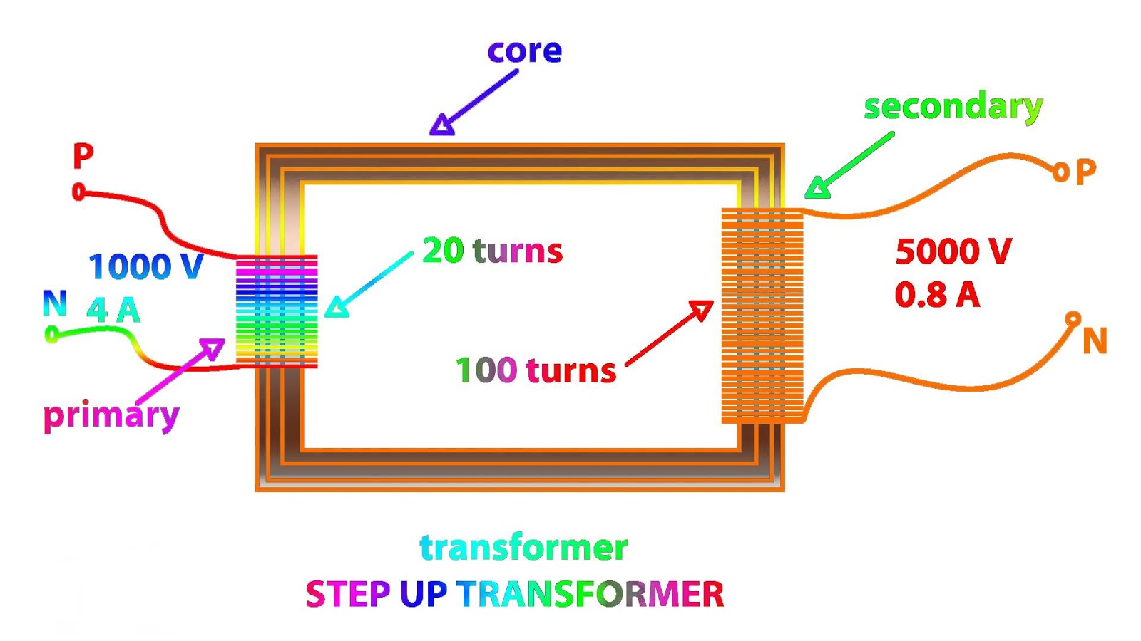
Schematic diagram of the transformer. A schematic diagram of a step-up transformer is shown in image 2, wi th T 1 and T 2 representing the turns of the primary and secondary windings and V 1 and V 2 representing the in put and output voltages, respectively. The transformer's output winding is the secondary winding, whereas the primary winding is the transformer's input winding. In this video, Emma Dent will demonstrate how to use a step-up and step-down transformer. Step-up transformers boost the size of an alternating potential difference, while step-down transformers do the opposite, reducing it. You will need: 0-15V Laboratory Power Pack (AC Output) Digital Multimeters Wires and Crocodile Clips Transformer Coils Bulb Circuit - […] A transformer designed to reduce the voltage from primary to secondary is called a step-down transformer. The transformation ratio of a transformer will be equal to the square root of its primary to secondary inductance (L) ratio. RELATED WORKSHEETS: Step-up, Step-down, and Isolation Transformers Worksheet
Step up/Step down Transformers explained in under 10 minutes Circuit Diagram
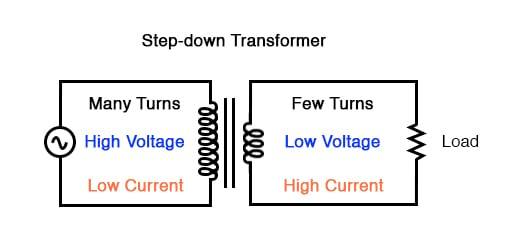
Step-down transformer: (many turns :few turns). The step-up/step-down effect of coil turn ratios in a transformer (Figure above) is analogous to gear tooth ratios in mechanical gear systems, transforming values of speed and torque in much the same way: (Figure below) Torque reducing gear train steps torque down, while stepping speed up. A boost converter (step-up converter) is a DC-to-DC power converter that steps up voltage (while stepping down current) from its input (supply) to its output (load). It is a class of switched-mode power supply (SMPS) containing at least two semiconductors (a diode and a transistor) and at least one energy storage element: a capacitor, inductor

The step-up transformer gives the higher voltage as a output because the voltage is directly proportional to the number of turns in the windings. Hence, in a step up transformer with N 1 turns in primary winding, It increases or steps up the voltage in the output circuit. It decreases or steps down voltage in the output circuit. Effect on