Triac dimmer Circuit Diagram Light Dimmer Circuit Using Triac. This light dimmer circuit is built with various electrical and electronic components like resistors R1=68 kilo ohms, R2=280 kilo ohms and R3=10 kilo ohms, variable resistors VR1=100 kilo ohms and VR2=200 kilo ohms, capacitors C1, C2 and C3=0.33 uF/400V, TRIAC is BT136 and DIAC is ER900.

A simple Triac can do the work for you. Triacs are used in this circuit as a dimmer as they are easy to design and control, and are very much economic due to their high efficiency and low buying costs. This is the circuit diagram of the simplest lamp dimmer or fan regulator. The circuit is based on the principle of power control using a Triac. By carefully following this process and considering the safety precautions, you can successfully build a 220V AC light dimmer circuit with triac control. Adjustments to the potentiometer will allow you to control the intensity of the connected incandescent bulb. References: TRIAC dimmer, circuit design help (resistive load)
Circuit Diagram Of Light Dimmer Using Diac And Triac
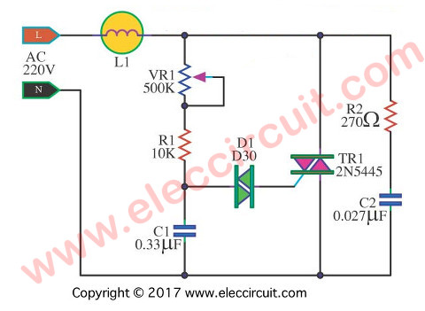
# 4: AC 100W Lights TRIAC Dimmer circuit. This is a simple AC TRIAC dimmer circuit. We can dim the lamp up to 100 watts. If the TRIAC is a high temperature. It should be held with a large heat sink. The DIAC(Diode AC bi-directional switch) is a kind of diode. It switches AC voltage or trigger to a gate of the TRIAC.

Working of Arduino Lamp Dimmer Circuit. Below are the pictures of showing three stages of dimming the AC bulb using Arduino and TRIAC. 1. Low dimming step . 2. Medium Dimming step . 3. Maximum Dimming step: This is how an AC Light Dimmer circuit can be built easily using TRIAC and optocoupler. A Working Video and Arduino Light Dimmer Code is
Simple 220V AC Light Dimmer Circuit Circuit Diagram
In this tutorial we will design a circuit using TRIAC and optocoupler to make a 220V AC Light Dimmer or AC Fan Speed Controller using Arduino. WARNING: This circuit is connected directly to the mains AC voltage. You must care about all safety precautions before using the device. The Diac and Triac can be connected in one of two ways to create a light dimmer. In the first, a DC voltage source is fed into the Triac, and the output of the Triac is connected to the Diac. The Diac then controls the amount of power being sent to the light bulbs.

Improved Design. The AC light dimmer circuit illustrated below incorporate the necessary precautions for subsiding the above issue. Hi sir., Pls clarify whether the triac or diac in the first simple triac dimmer circuit needed any dc voltage for their activation. In the circuit diagram, no such sources are shown.

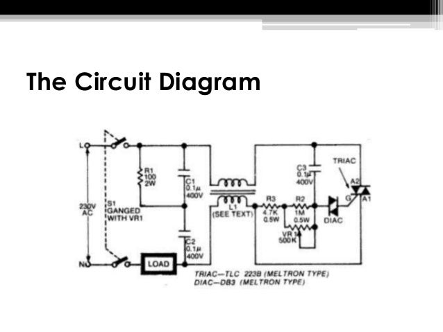
Engineering 101: Light Dimmer Using a Triac and Diac Circuit Diagram
The circuit diagram presented above is an classic illustration of a dimmer switch, where a triac continues to be employed for managing the depth of light. When AC mains is provided to the above circuit, as per the setting of the pot, C2 charges fully after a specific delay supplying the necessary firing voltage to the diac.
