Wireless charging in mobile phones management systempdf Circuit Diagram The ease with which the charger can quickly put a portable device in a charging state, is driving growth in the mobile and wearables markets. In addition to consumer devices such as smartphones and smartwatches, medical products such as blood glucose monitors and industrial bar code scanners are transitioning to wireless charging. Furthermore Wireless power transfer allows a convenient, easy to use battery charging of mobile phones and other mobile devices. No hassle with cables and plugs, just place the device on a pad and that's it.
Wireless Charging Solutions: Design of Mobile Device Transmitter Receiver Load Power Control Mobile Device •Contains a receiver that provides •Charging circuit capacity •Semiconductor device rating . COMPANY PUBLIC 16 Receiver Group Based on Applications 5V/0.1A Applications

PDF Design of a Qi Wireless Charging Device Circuit Diagram
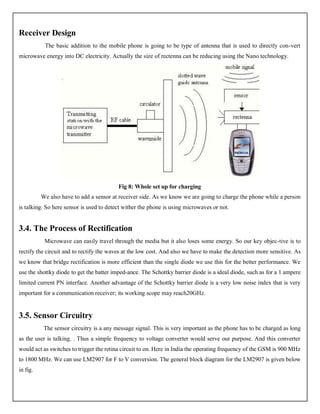
The rectifier circuit is responsible for converting the alternating current generated by the wireless charging module into direct current that can be used to charge the mobile device. Using the specified components, build the rectifier circuit according to the provided circuit diagram. the receiving device (such as mobile phone), a minimum of 0.5mm of distance is required to reserve for the surface of the coil and the inner surface of the housing, so the thickness of interface surface of the housing should design within 1.25~2.0mm. The design layout of PCBA/transmitter coil/receiver coil will directly affected the debugging of
allows charging devices to easily adapt to changing power levels. This is important to ensure compatibility with different types of consumer electronics devices, such as smart-phones and tablets. Qi Wireless Design Overview: The principle of wireless power transfer in basic terms is an open-air transformer consist- Protecting the wireless charging pad. The wireless charging pad power input is either a USB Type-C port or a proprietary DC input (Figure 6). Be sure to protect the DC input circuit from both overloads and transients. Protection is still necessary for the design, regardless of the power input in use.

PDF Wireless Charging Solutions: Design of Wireless Charging Circuit Diagram
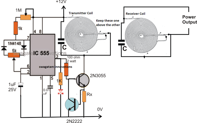
designs a simple wireless battery charging system which charges a mobile phone when placed near the wireless power transmitter. A PROTEUS based simulation of the proposed prototype has been investigated before design of the actual hardware model. The present design may be utilised for wireless power transfer (WPT) system, wireless mobile
